CUB electrical and Lighting upgrade
| Client: | Personal project | ||
| Built: | 07.2017 | ||
| Work |
|
||
Introduction
Is the scariest electrical jobs I have done on this bike, however one I'm very happy to have completed and one that has taught me a lot about its wiring that would help me later on an adventure ride I did.
Background
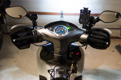
This modification is one of many done to my Honda Wave 125i to make it more comfortable on long adventure rides. It came about when I installed Oxford Heated grips and noticed after a 20 Minute ride to work that the low battery indicator on the grips began flashing even though the bike was running.This has prompted me to investigate the charging output and how to improve it.
The main goals were to:
- Increase effective electrical output to:
- charge equipment on the way (laptop, drone, slr)
- run heated grips
- Run extra bright LED headlights
Charging System Upgrade
The upgrade of the rectifier was necessary not to gain a lot more power from the stator (the windings remained unchanged), but to allow a drop in constant power consumption.Out of the box it was not possible to replace the inefficient incandescent 35W+35W bulbs with LEDs due to the bikes charging circuit.
Initial investigation
As the motorcycle is an import from Thailand there is only limited information about the charging circuit and possible upgrades. While there was some online documentation available, doing additional investigation together with a friend of mine who helped out with his Oscilloscope was necessary.
It was then that we finally learned how the circuitry works.
As the motorcycle is an import from Thailand there is only limited information about the charging circuit and possible upgrades. While there was some online documentation available, doing additional investigation was necessary. Together with a friend of mine who helped out with his Oscilloscope to gather a better understanding of the rectifiers operation.
Rectifier wiring
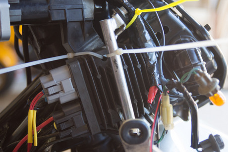
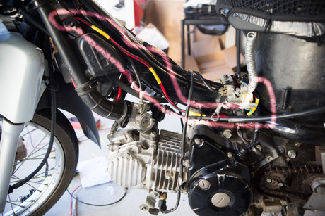
This however still left another problem as the OEM rectifier had more wires going in/out than it seemed necessary. From the wiring diagram we already knew that one was supplying the headlight circuit.
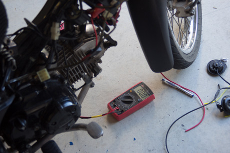
However that still left 2 further wires. Using the diagram and a conventional multimeter we identified them as well.
OEM Setup - Documentation
After we finished our investigation, this is the information we gathered.Charging System basics:
The charging system runs single phase off the stator where one wire is grounded with the chassis.The complication begins after the rectifier as the motorcycle turns out to have 2 main circuits based off the stator output.
- Upper half of the wave for the DC circuit (ECU, indicators, battery,...) using negative ground.
- Lower half of the wave that gets send as DC pulses (pretty much AC) using positive ground.
- The AC positive ground output on the headlight circuit makes it impossible to run LED or HID headlights.
- The DC circuit only made use of half the Wave and couldn't supply the load either.
Rectifier Wiring
We figured the wires on the Thai spec Honda Wave 125i are as follows:- Input wire from Stator
- Ground (also shares other wire from stator)
- DC positive output to battery
- AC negative output to headlight (positive comes from ground)
- Input trigger from ignition barrel
- Output to activate EFI/ECU (disconnecting it acts as engine cut off)
The last two worried us and prevented starting the bike without the rectifier engaged (run off battery alone). We initially triggered it with an inline fuse (a scary moment as we didn't want to fry the ECU).
Solution
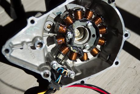
The solution was to float the stator (disconnect the grounded wire from ground) and replace rectifier with a Shindengen FH020AA Mosfet rectifier. While rather expensive, the unit promises to run more efficiently when compared to conventional shunt rectifier.
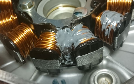
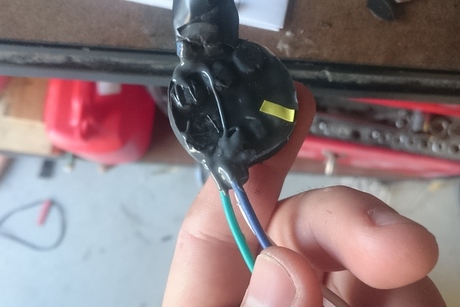
IMPORTANT:I originally opted for standard 5 minute epoxy so further stabilise windings. This turned out to be a mistake!
Most epoxy glues are not rated for high temperatures and will slowly degrade at high temperatures. Being an air cooled engine and the stator producing heat as well, temperatures could potentially reach or even exceed 160℃C.
The solution was to remove all of the old epoxy and replace it with JB-Weld (rated to constant 260℃C).
Additional Rectifier Wires:
- The engine cut-off was simply bridged with the ignition wire.
- The headlight wire was rewired to get DC positive from battery via a relay (I used a Hella 20Amp mini relay). Ignition served as a trigger for the relay.
As part of this upgrade I also fitted a volt meter that would engage when ignition was on to aid with troubleshooting.
The final task was to upgrade my lighting and included:
- Rewiring my LED spot lights (since the polarity changed to negative ground)
- Replace all running and instrument bulbs with LEDs (each saving a good few Watts)
- Upgrade the headlight to LED
Headlight LED upgrade
Upgrading the headlight from basic incandescent bulbs to LEDs gave me 2 major advantages.
A brighter headlight and far reduced power consumption at low beam (22W vs 70W), thus freeing up valuable reserves to run other equipment such as heated grips.
Challenges
Sadly, even with the high popularity of LED upgrades, it's still not a straight forward swap in 2018. Common reasons include:- Quality issues with available upgrade kits
- Currently there are only very few kits from major manufactures such as Philips
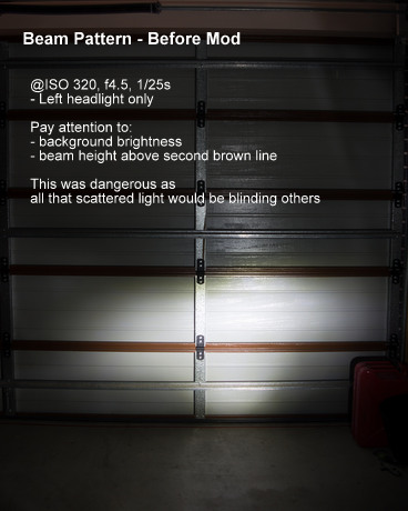
- Low Beam is too high or spread too far
- Low beam is way too bright or draw too much power (some lights exceed 40Watts on low beam)
- They would blind other road users
- They could also melt the headlight housing
- Wattage numbers are not clear (some lights are advertised as 170 Watts ore more)
- Fitment is not guaranteed (power supply and cooling fins need space)
- My Thai spec motorcycle used a less common M5 socket
- Skewed reviews
- Many small manufactuers and sellers bully customers to leave positive reviews
Chosen solution
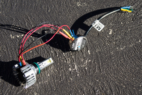
After trying out a number of different bulbs, I settled for M3s - 32 watt lights as they came with the correct adapters for my sockets (M5), had the right wattage and their great reviews on Amazon. These are also very commonly found on Amazon, eBay and AliExpress.
Problems
While these lights seemed near perfect for my needs, they were unusable right out of the box.- Their beam pattern was downright dangerous as it was blinding other traffic.
- The power supply in the back was hitting on the handlebars
- They used too much power on low beam
Modifications
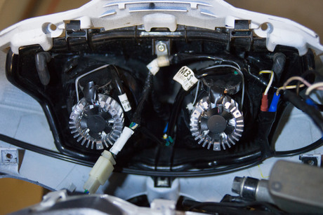
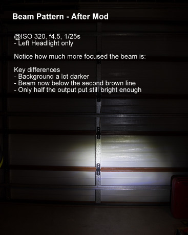
To get these lights to work properly and safely, the following mods were necessary:- Rewire to only trigger one LED on low beam (all 3 run on high beam).
- Rotate the bulbs so the active low beam LED would shine straight up in the reflector.
- Add baffles on the low beam LED to focus the light straight up.
- Remove the power supply to another position.
- Add Epoxy on the soldering joints as they were prone to break off the PCB.
- Cut channels into the heatsink so the power supply can be relocated.
So far In only encountered 2 problems that I rectified since.
- The Hella relay stuck in the closed position on one ride (I replaced it since).
- An additional spot light switch I installed developed a weak contact after one year as it wasn't waterproof. I replaced that since then.

