CB500X Heated Grips, Spot Lights and 12V Outlet
| Skills Required |
|
||
| Materias and Equipment |
|
||
Backround
Good lighting and a way to charge Equipment (usually phone / GPS), are essential.
Heated Grips, make for a far more pleasant experience in cold weather.
I won't go too deep into the installation of the 12V outlet and Oxford Grips, there's already enough information out there.
I believe in the Japanese design phylosophy of Poka Yoke, or mistake proofing.
With that, the installation goes a little beyond the standard setup that most opt for, for additional convenience and to improve battery longevity.
Modern Motorcycles
In general, vehicles that were designed in Japan are built using relatively "simple" engineering.
While they often end up being less sophisticated than their european counter parts, they are usually eaiser to service and more suitable for modifications and improvements from the aftermarket.
Sadly, the CB500X hasn't been immune to some modern engineering and cost cutting.
This includes reduced the wire thickness to the minimum specifications. Something that can be overcome with Relays.
Electrical Setup
Ignition Relay
Depending on the Model and desired setup, we need 2 (or 3) Relays.
One Master Relay will be needed to power auxiliary electrics such as 12V outlets and heated grips.
While many electrics like Oxford Grips use smart controllers, it does note make them immune to parasitic drain on the battery. The grips can alos run longer than needed when switche doff.
A safer method is to just disconnect all unneeded components with Ignition. This is particularly true for USB chargers, where some can drain the battery over night.
The power out of that relay will also serve as the base power for the spot lights.
To power all electrics, we'll need to pull a heavy enough wire to that relay (easy enough under the fairings). I used an inline fuse holder and placed a 15 Amp fuse in it.
In my case used the battery terminals for + and -. A cleaner way would be to use the main ground point on the bike on the left.
2013-2015 Models
Owners of the 2013-2015 Model are in luck, as they can upgrade the headlight by replacing the bulbs with LED'simprove the Headlight and utilise older wiring. For ignition, they also have the option, to tap into the small "Park" or fallback light. Particularly into the cable label No. 3 in the Diagram. Part No: 33120-MGZ-J41.To get a simple High Beam signal, they can use a H4/HS1 extension/splitter cable and tap into that (minimising impact on OEM wiring).
2016 Models and Newer
Owners of the 2016 facelift model (like mine) and newer, do get the pretty LED Headlight. While it's most likely never going to burn out, it's not all that bright or versatile.
The biggest issue is its proprietary connector, which denies easy access to an ignition and Hi/Lo signal.
Messing up a hackjob on the main wiring harness would be a disaster to fix. Tapping into the (retail) $375.13 LED headlight is not ideal either.
That's particularly of importance to those that want to preserve their warranty.
But, there's a solution to all the issues!
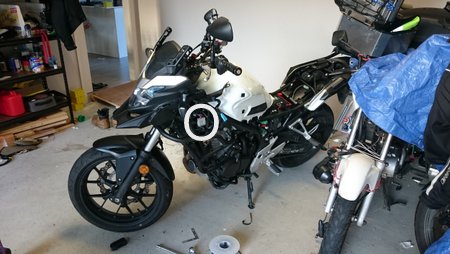
Left Switch-Gear
Not only does have a line going in with that powers up on Ignition, it also has a line going out, to indicate the Hi/Low beam position.
At $44.25 retail, it's one of the cheaper components (in case something does go wrong).
The best position to tap into is just above the connector. While I don't remember the exact wiring, it's easy enough to probe the connector with a Multimeter.
- Place negative terminal on Ground
- Turn On Ignition
- Probe each wire till you find one that's live
- Toggle all the switches (including Clutch Lever) to ensure it stays live (truly ignition)
- When toggling Hi/Low Beam remember that wire
To tap into the wiring, I used a Stanley Knife and carefully soldered on my piggiback/bodge wires off ignition and the Hi/Low wire.
Reversed High Beam + Additional Switch
An annoying "feature" is the reversed High Beam signal (12V = low beam, 0V = high beam). A solution to it is the "normally closed" pin (usually 87a) can be utilised to reverse the Signal. The power input has to come off the ignition that fires with Ignition.
See wiring diagram below:
Dedicated Spot Light Switch
If the low beam ever fails, this will allow running High Beam only without burning everyone's retinas with the spot lights.
That's particularly useful on older Halogen Bulb models bikes.
Another Relay?
While the switch that I have bought works well enough, my confidence in its reliability to run the 4x10W LED spot lights is not the highest. Considering the thin wiring, I decided that a dedicated relay would be a safer solution as the switch would be boosted by the ralay and itself would only see a few milliamps.You - can't negate nothing:
I pondered on the option to only run 2 relays. However, using the direct signal off the Hi/Lo Wire is also not possible without first inverting it.
Simply, because the signal is 0V on high beam we can't distinguish the switches On/Off position when we want it.
Lights and placement
I always thought that the Givi Crash bars would make for a good mounting platform to install spot lights.
After some experimentation, I settled for 4 TMH branded 10W spot lights. Not only did I have good experience with similar lights in the past, but mainly do they fit withing the outside boundaries of the Givi Crash Bars.
I looked at 20W mini light bars, but they would have been hitting the motorcycle fairings with every fall.
To mount the lights, I simply used Pole Clamps from Bunnings that are padded with strips of motorcycle inner tube.
Final Result


